Mark III Camera Details
The Mark III Camera is headed for the big pond. The problem is that the big pond is
much larger than the old pond, and hence the number of fish per viewable volume is much
smaller. This led me to thinking of doing a steerable camera (i.e. support panning). This
would allow a larger volume of water to be examined, and hence it would be more
likely that a fish would be spotted. I also have plans to add tracking of fish -- the
fish detector already can spot a fish, and the feedback loop just needs to be closed.
The camera uses the same module as the Mark II. However, it is now mounted on top of
a small RC Servo (a DF-09 at around $10).
This is controlled by a FT639 servo controller. This device takes a 2400 bps serial line and produces
the pulses required to control (up to) 5 servos. The original plan had both pan and tilt, but the mechanics got too complex.
One of the big difficulties was finding a clear dome to house the camera and servo. Eventually, I found
some surplus plastic display domes that were just the right size. I had tried glass ones and various other
things, but none of them were optically smooth. [Annoyingly, I did see a Christmas Snow Globe in the local Christmas Tree Shops Shop which would
have worked just fine (after I threw away the contents). However, I didn't buy it -- and I regretted it ever since.]
I made creative use of silicone caulk to fill in the gap between the dome and the plumbing part that houses the electronics.
The camera will be on the end of about 250 feet of cable. This is partly to allow for repositioning the camera in the pond, and partly because
the server is at the opposite corner of the house (and there is no straight wire run).
I'm using direct burial CAT5e for the outdoor runs, and regular CAT5 for the indoor runs. I'm using one pair for video, one pair for the control serial channel, and the other two pairs for power and ground. CAT5 has about 9Ω/100m resistance. By doubling up the power supply pairs, I end up with an effective 8Ω in the power supply line. The camera itself takes under 30mA at around 9V, and I have no idea what the servo takes -- but that is at a regulated 5V. I anticipate using
a 12V feed, and not losing more than 2V in the cable. That sort of loss would only apply when the servo was moving.
Mark II Camera Details
The Mark II camera replaced the one described below after the Mark I died
during a thunderstorm. I replaced the camera itself with a CMOS camera module
(a C3186A from Amazon Electronics)
that does 640x480 resolution. I don't really know why I did this, as I only
ever capture at 320x240! Those modules are noticeably cheaper. Supercircuits are a good source
for this kind of stuff. For example the PC103XS
is 640x480 CCD camera that I also bought.
I'm now using glass at the front for the viewport. This is actually electrically
conductive coated glass -- this will be useful when I try out the 'electric
current prevents algal growth' theory.
I've also changed over to using ffmpeg as the server. This allows
me to serve streaming video in a number of formats and it seems to work well
(though it needed a lot of fixing). The current (mid june 2002) CVS version
is OK. I have added the text overlay that gives the time and temperature.
The fish detector is also custom code in ffmpeg.
The housing for the camera is also now painted black to make it less obvious
when it is in the pond.
Mark I Camera Details
The camera came from the X10 people -- they sell stuff really cheaply, but
they send you emails every night to tell you about their latest deal. Since
I've bought more stuff from them, I suppose it must work!
The actual camera came with a 12ft wire that terminated in an RJ11 plug.
It turned out that the pairs in the cable were for power, video and audio.
The video is standard NTSC, and the power was some DC voltage -- but there
is a regulator inside the camera. Anyway they provide the wall brick.
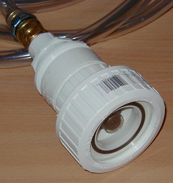
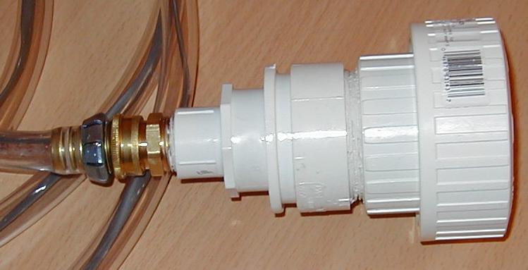
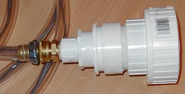 The housing was constructed from a bunch of Schedule 40 plumbing parts.
One end is a 2inch union and it gets progressively smaller down to a standard
brass hose fitting at the other. All the pieces in between were used to join
those two together. Much time was spent staring at the rack of Schedule 40
parts in Home Depot trying to get a reasonable set!
The housing was constructed from a bunch of Schedule 40 plumbing parts.
One end is a 2inch union and it gets progressively smaller down to a standard
brass hose fitting at the other. All the pieces in between were used to join
those two together. Much time was spent staring at the rack of Schedule 40
parts in Home Depot trying to get a reasonable set!
It turned out that the only union that they had had screw threads -- so
this added to the confusion somewhat!
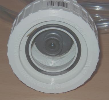 I then threw away half of the union and cut a piece of pexiglass to fit
in its place. The sealing ring still performs its function. This picture
is not the best, but you can see the camera lens (fixed focus -- more on
that later) and the rubber sealing ring. The pexiglass is invisible, but
covers the entire front.
I then threw away half of the union and cut a piece of pexiglass to fit
in its place. The sealing ring still performs its function. This picture
is not the best, but you can see the camera lens (fixed focus -- more on
that later) and the rubber sealing ring. The pexiglass is invisible, but
covers the entire front.
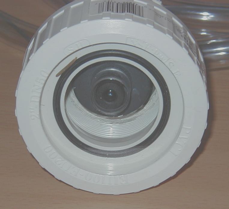
This is a view looking into the business end of the completed camera/housing.
 The wire from the camera was threaded out of the brass hose fitting and
down a length of hose into a dry (ish) area where it connects to a video
cable into the house and onto a video capture card.
The wire from the camera was threaded out of the brass hose fitting and
down a length of hose into a dry (ish) area where it connects to a video
cable into the house and onto a video capture card.
The camera is fixed focus -- I reckon about three feet to infinity. This
is clear not good for a pondcam, so I added a +2 diopter (500mm focal length)
plano-convex lens
to bring the focus in (a lot). Finding a small lens that would fit between
the lens of the camera and the pexiglass was a significant problem, but eventually
I went with Control Optics.
If anyone else builds a camera like this, then please let me know at
the address below!
Video Capture and Serving
The video cable runs about 100 ft into the house into an AverMedia TV98 card
(this is a generic Bt848 based card that was on sale at CompUSA). I used
RG59 coax for the long run -- this was mostly driven by the fact that I had
undersized my underground conduit (1/2in pipe) leading out to the pond. It
can only just hold two CAT5 cables and the RG59. My advice would be to use
3/4inch pipe and all long throw bends.
The video capture card is in a Linux box running SuSe linux (mostly because
they send me free copies as I am a long time kernel contributor -- in fact
Linux Journal ran an interview with
me in the June 2000 issue).
I use CAMSERV as the server
for the video stream. I added some extra code to do fish detection (based
on colour), and this drives the images that go into the gallery.
Dallas Semiconductor Instrumentation
The graphs for the weather are drawn with gnuplot from a database. More on
this in the future.
It turned out that there was a bug in many of the libraries distributed
to read the temperature from the Dallas DS1820 temperature
sensor. The patch here fixes those problems --
it probably won't apply to anything that you have, but it should start to
appear in the standard libraries near you soon. The problem manifests itself
as occasional erratic temperature readings -- it was actually due to a timing
problem during the conversion cycle.
Last updated: June 15, 2002
Philip Gladstone
 The housing was constructed from a bunch of Schedule 40 plumbing parts.
One end is a 2inch union and it gets progressively smaller down to a standard
brass hose fitting at the other. All the pieces in between were used to join
those two together. Much time was spent staring at the rack of Schedule 40
parts in Home Depot trying to get a reasonable set!
The housing was constructed from a bunch of Schedule 40 plumbing parts.
One end is a 2inch union and it gets progressively smaller down to a standard
brass hose fitting at the other. All the pieces in between were used to join
those two together. Much time was spent staring at the rack of Schedule 40
parts in Home Depot trying to get a reasonable set!